Monday, 28 February 2011

Artifact 3 - Goldeneye Train

Goldeneye Train

The Goldeneye train will form part of the animation. The train will enter the scene appearing from under a bridge and then explode, using a similar technique to that of the 007 logo.
Goldeneye Train Construction

The Goldeneye train was constructed mainly from basic shapes such as rectangles, triangles and boxes. All of these shapes were formed into ‘editable polys’ to that they could then be sculpted into the desired shape. The train was constructed in stages, the front first then middle and finally the rear. The wheels and additional features such as hand rails etc were also constructed in separate stages.
After completion of each stage, the individual stages were imported and merge into one bringing the train into one complete 3DS Max file.
The train and its shaping were sculpted with the aid of an image set aside to the 3DS max program and was sculpted using eye reference only. This was due to the fact that no appropriate images could be found in order for the train to be constructed with bitmapping and planes techniques.
Train Wheels Construction

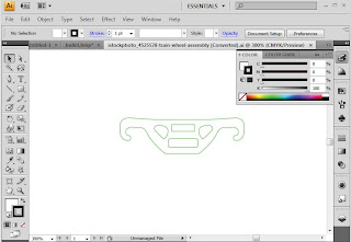
The train wheels were constructed from a real life image of train wheels. This image was then imported into illustrator and then using the pen tool an outline of the train wheels was then produced. This outline was imported into 3DS Max and with the use of the ‘extrude’ tool the wheel structure was produced and texture with images of rusty metal with the material editor.
The wheels themselves were also constructed in a similar way. Half the outline of a train whe
el on a 90 degree angle and then constructed in 3DS Max with the lathe tool.
The springs that from the suspension were made using the spring tool within 3DS Max, the number of coils were edited using the modify tool.
Once the construction of the’ train wheels’ were complete the entire model was imported into the Goldeneye train file to finalise the train model.
Train Track Construction

The train track was formed in a similar way to that of the Goldeneye train itself. Constructed with the aid of shaping using the modification of the ‘editable poly’ tool.
Materials imported as bitmaps and added as texture using the material editor.
Once completed the track is merged with the Goldeneye Train to give the effect the Goldeneye train is running along rails.


Artifact 2 - 007 Logo

007 Logo

This 007 logo will be the feature that the bullet will pass through once it is fired from the gun. The 007 logo will shatter into pieces as it is stuck by the firing bullet tip.

Construction of the 007 logo
The construction of the ‘007 logo’ first begun as an image taken from the web. This image was then imported into Illustrator and using the ‘Trace Tool’ the outline was traced to give an accurate outline of the logo. This outline was then imported into 3DS Max and using the ‘Extrude’ tool the logo was crafted into a 3D model. Materials were added via the material editor using the textures from bitmap images of rusty silver metal.

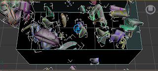
To break the 007 logo into pieces to look as though the bullet had smashed the image part the logo was first lined into sectors using planes. This can be seen in the image above. Using the aid of the ‘Procutter’ tool the logo was sectioned into alternative segments broken via the lining of the planes.
Using Procutter

Using Reactor Property Editor


Using the Box Effect


A box was then constructed around the logo with the top removed and then flipped inside out. Using the features of the Property Editor from the ‘Animation Reactor Sector’ the logo was set to explode on an impact determined by its mass and Simulation Geometry set to Proxy Convex Hull and the box itself set to Concave Mesh.  
In an simulation the segmants of the logo will now explode into sectors and be placed around the scene in life like positions. The box will be deleted .  
The tip of the bullet, constructed in the construction of the gun element, will now be used to smash through the logo and with the animation in place it can be seen in a life like simulation.


Artifact 1 - Bond Hand Gun (Walther PPK)

Bond Gun – Firing Bullet

The Bond Gun displayed above will build the beginning of the trailer. The Bond Gun will fire a bullet that will travel through the scene and smash its way through the 007 logo.
Construction of the Bond Gun
The Bond Gun is constructed of many shapes that have been edited with ‘Editable Poly’. The gun was drafted off a replica drawing that was used as a bitmap displayed on a plane to enable myself to shape sectors of the gun so that they would look correct. The basic shape of the gun begins with the use of the ‘Box’ tool to create differently sized rectangles. These rectangles were then converted into ‘Editable Polys’ so that the rectangle could then be shaped using the move tool on particular sectors of the poly. Once the desired shaped was achieved it was then aligned using the ‘Align’ tool to align it to the other shapes so that they all matched a similar height. The sectors that were crafted from the ‘Box’ tool were the handle, trigger and surrounds and the cocking/barrel shaft. The gun was originally crafted on one side so that once finished, it could then be duplicated to create the other side so that the gun will look symmetrical when view from all angles. 
The barrel and other rounded sectors of the gun were crafted using the ‘Cylinder’ tool. Once the cylinder was crafted into the desired shape it was then converted into an ‘Editable Poly’. Using the ‘Border’ tool the inside of the cylinder was removed and the outer border was dragged to the desired length. This was the same for all of the sectors using the cylinder tool as it gave control over the desired shape and was easy to achieve a barrel like shape.  Material applied using the material editor and text applied from the use of the text tool from the shape menu.
The bullet was constructed via the Lathe tool. An image of a bullet was imported into Illustrator and using the pen tool half the outline was drawn. The original image deleted and the illustrator image was imported into 3DS Max as an Illustrator 3 file. Using the lathe tool the half image of the bullet was constructed into a full 3D model of the bullet. A gold material was applied to the bullet and then the top was split from the bottom of the bullet and placed into position on the gun. In animation the gun will look as though it is firing the tip of the bullet as the bolt will shoot back sending the tip of the bullet out of the barrel and the discharged shell of the bullet out of the side of the gun.

Use of Lathe

Saturday, 26 February 2011

Week 5 - Camera Angles and |Materials

Week 5 – Camera Angles


In this tutorial I learnt how to work with the use of Cameras in 3DS Max. The camera types that I covered today were the ‘Free Camera’ and ‘Target Camera’.
The ‘Free Camera’ enables the user to create a camera that acts as though it’s a portable camera. This enables the camera to be used anywhere on the stage and it has the ability to be free but does have restrictions in the fact it cannot be used to create particular effects.
The ‘Target Camera’ is a fixed camera and has similar abilities to those in a studio. It can be moved around but with limitations on movement. It however does have the ability to be targeted onto particular objects and this will prove incredibly useful with my animation as my animation will feature lots of moving objects. Accurate camera angles will prove vital in my work.
Both of these types of camera can be edited with the aid of the modifier tool. Modifications such as lens size and depth of field will be the most common modification used within my animation. These styles of modifying can be seen in the images above.
The view from these cameras can be seen when rendering if the user is to select and change the viewport on the rendering screen or via the on stage view point. 
To change the viewpoints of any of the cameras the camera view can be selected and then adjusted via the modifying tools such as the Orbit, Perspective, Dolly and Truck camera adjustments. 

Also in this tutorial I learnt how to create the effects of glass and creating chrome effects as materials on objects. The glass feature is particularly useful when creating my animation as much of my featured designs will contain some form of glass. These particular material effects can be seen in the image above.


Wednesday, 16 February 2011

Week 4 - Light Effects

Lighting Techniques

In this tutorial I learnt the different styles and types of lighting techniques that can be used within 3D Studio Max. The lighting that we covered was Omni and Target Lighting. There was also some briefing over the others but these were the main featured ones that will be most common in my animation.
In the image above an Omni light has been used inside the pumpkin along with a target light on the exterior with colour changes and noise levels adjusted in order to give a smoke effect to the ray of light.
The lighting techniques that I learnt were how to change the colours and intensity of the lights and the aiming and adjustments of the positions and colouring. Also in the featured image I have used shadowing techniques too in order to produce a more detailed effect.
In the image a selection of Omni lights have been positioned around the objects each giving off a different colour of light effects. Some of the objects have been modified to be excluded from the beams of particular lights, this is another technique learnt in the tutorial.
I also learnt in the tutorial the use of using chrome effects and Mental Ray Rendering. This use of Mental Ray Rendering was the effects created from Arc and Design Materials and Skylight background effects. In this image, the objects have been placed in a field of what is to look like natural sunlight created from lighting effects in the daylight system. Here adjustments to the time of day and where in the world the particular light is being replicated from i.e. Mexico etc. The objects have been covered in materials used from the Arc and Design in order to give the representation of natural sunlight and the skyline being reflected off them.

Tuesday, 8 February 2011

Week 3 - Bitmaps and Materials + Research Board


Week 3 – Loading Bitmaps and Materials

 
In this tutorial I learnt how to load bitmaps into 3DS Max and use them as texture on particular materials. There were extra features that I covered such as loading the bitmaps and editing them via the ‘Bump’ tool in ‘Maps’ from the material editor sector. This enabled the texture to appear to have a 3D texture to it and look more real life. I found that this feature of texture and materials would be extremely valuable to my animation project as much of my animation designs will rely on the texture of the objects looking as real life as possible.

 
One of the exercises on this tutorial was to create the image above. This was done partly via Adobe Photoshop to create a black and white background. After creating this it was imported into 3DS Max along with the original and used as a material with the aid of the ‘Opacity’ in ‘Maps’ from the material editor.  This enabled 3DS Max to create this as a material that could then be placed on a plane and edited in such a way that it would look like a tree. I found this feature also very useful as at some point I was expecting to create some form of leaf to create trees and bushes in my animation project.

Goldeneye Research Board

Above is the Research Board for my chosen project. The trailer that I will animate will be based on the 1995 James Bond Film Goldeneye.

The 3 chosen Artifacts that will be constructed for Assignment Part 1 will be -

  1. Goldeneye Train
  2. Bond Gun 
  3. 007 Bond Logo


Tuesday, 1 February 2011

Week 2 - Use of Lathe and Shape Editing, Intro into Bitmapping


Use of Lathe and Shape Editing, Intro into Bitmapping

Here is a chess piece that I made with the aid of Adobe Illustrator. Using Illustrator I imported a 2D image of the chess piece (only as half an image) then imported into 3D Max to turn it into a 3D image.
I found this progress has assisted me with developing better skills in 3D modelling.


Above is a tank that was design from importing a 2D image of the structure of a tank in line format. The tank was then constructed using shapes and editing these shapes.